Thread End - Series: 07
Thread End - Series: 07
Size:1" thru 4"
Operating Temperature:To 225°F with standard materials
To 300°F with optional materials
Maximum Differential:5 psi
Maximum Containment:25 psi

Design Standard
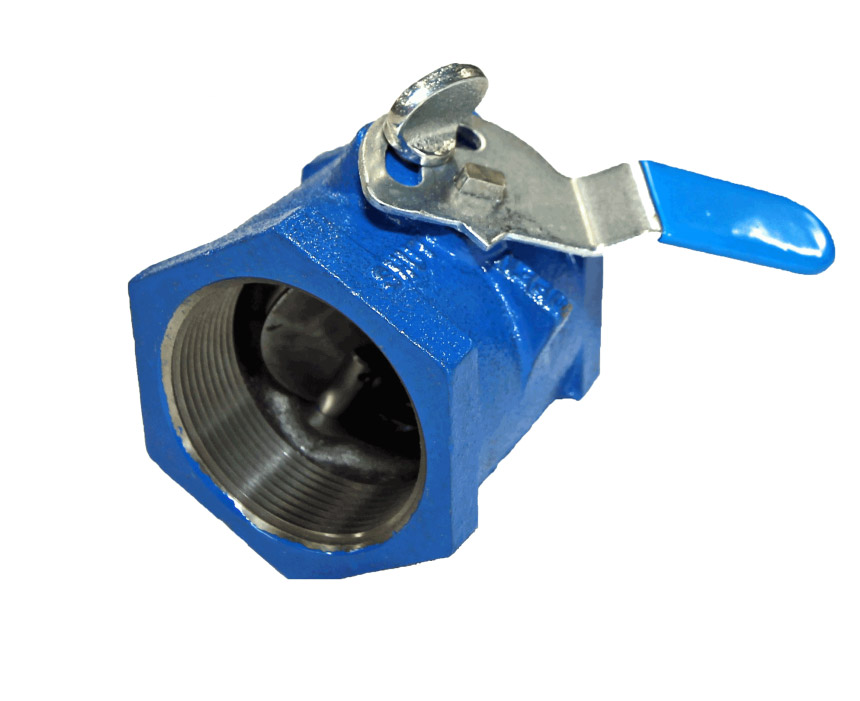
The PDC “Thread End” Series Butterfly Valve is available in sizes from 1″ thru 4″.
Specifications
Size Range:
1" thru 4"
Temperature:
To 225°F with standard materials
To 300°F with optional materials
Body Style:
Female Threaded Pipe
Design Features
- Simplicity of construction
- Close tolerance angle seated disc machining for minimal leakage.
- Thread end construction provides maximum economy by eliminating need for mating flanges.
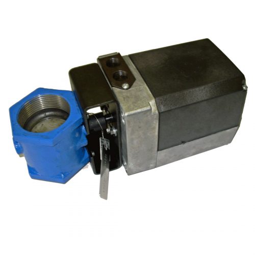
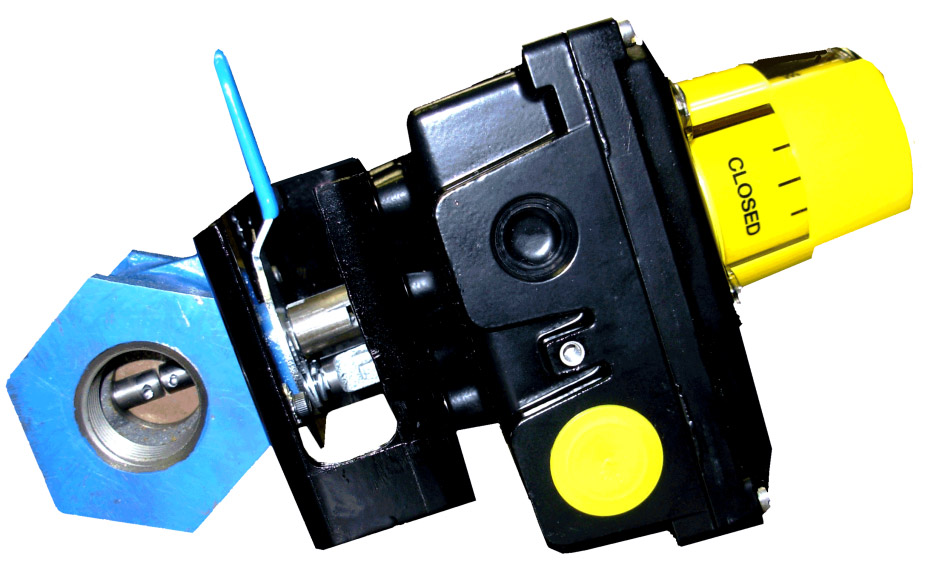
- Thread end valves can be customized for electric and pneumatic actuation.
Applications
- Blower Equipment
- Compressor Equipment
- Boiler Equipment
- Environmental Systems
- V.A.C
- Industrial Process Furnaces
- Oil Gas/Refining
- Power Generation/Co-Generation
- Water & Sewage
- Stationary Engines
- Chemical Equipment
- Mining Equipment
- Gas Recovery Systems
Standard Materials and Seat Construction
| Body: | Cast Iron |
| Disc: | Carbon Steel |
| Shaft: | Stainless Steel |
| Seals: | EPT O-Rings |
| Seat: | Angle |
Optional Materials and Seat Construction
| Seals: | Viton O-Rings suitable for temperatures to 300°F |
| Seat: | Swing Thru |
Chart or Graph
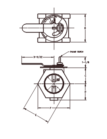
Typical Dimensions: 1″ thru 4″
Style A
Thumb screw friction lock permits an infinite number of disc positions.

Style C
Locking handle friction lock permits an infinite number of disc positions.

| Size (NPT) | A | B | C | D | E | F | Approx. Wt. (Lb) |
|---|---|---|---|---|---|---|---|
| 1 | 1.04 | 2-3/4 | 1-1/2 | 1-9/16 | 2-1/2 | 2-7/8 | 3.5 |
| 1-1/2 | 1.6 | 2-3/4 | 1-1/2 | 1-9/16 | 2-1/2 | 2-7/8 | 3 |
| 2 | 2.04 | 2-7/8 | 1-5/8 | 1-11/16 | 2-7/8 | 3-5/8 | 4 |
| 2-1/2 | 2.44 | 3-5/8 | 2-1/16 | 2 | 3-1/2 | 4 | 5 |
| 3 | 3.04 | 3-7/8 | 2-3/8 | 2-11/16 | 4-1/8 | 4-3/4 | 6 |
| 4 | 4.02 | 4-1/2 | 2-7/8 | 2-15/16 | 5-1/8 | 5-5/16 | 10 |
MAX ∆P is 5 PSI. MAX containment pressure is 25 PSI
Cv Values for PDC Thread End Series Valves
By definition, Cv is the flow coefficient of a control device or flow restriction. Cv is defined as the number of US gallons of 60°F water per minute which will flow through the given restriction with a one pound per square inch pressure drop.n restriction with a one pound per square inch pressure drop.
Cv Values
(Flow in GPM of 60°F water at 1 psi pressure drop Specific Gravity=1)
| VALVE SIZE | Disc Angle, Degrees | ||||||||
|---|---|---|---|---|---|---|---|---|---|
| 10 | 20 | 30 | 40 | 50 | 60 | 70 | 80 | 90 | |
| 1 | 1 | 3.5 | 8 | 12 | 16 | 20 | 32 | 42 | 45 |
| 1.5 | 2.1 | 4.5 | 9 | 17 | 31 | 51 | 80 | 137 | 219 |
| 2 | 3.5 | 7 | 15 | 27 | 51 | 83 | 130 | 222 | 355 |
| 2.5 | 4.9 | 10 | 22 | 39 | 73 | 119 | 186 | 317 | 508 |
| 3 | 8 | 16 | 34 | 61 | 113 | 185 | 289 | 493 | 789 |
| 4 | 13 | 28 | 60 | 106 | 198 | 323 | 505 | 862 | 1380 |


