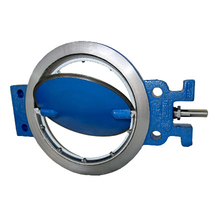
Medium Duty - Series: 01
Medium Duty - Series: 01
Size:2" thru 14", 16" thru 24"
Operating Temperature:To 450°F with standard materials.
To 900°F with optional materials.
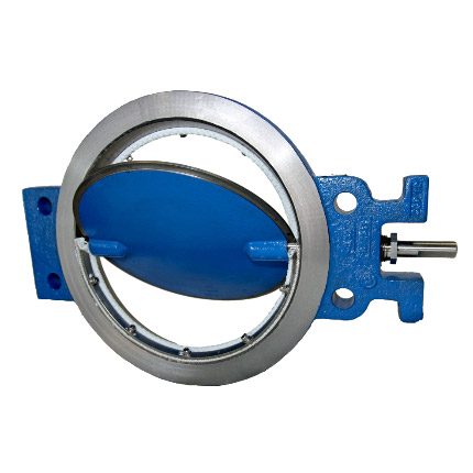
Design Standard
The PDC “Medium Duty” series butterfly valve is available in sizes from 2″ thru 24″ in a combination of materials and optional features suitable for most mid-range differential pressures and service conditions.
Specifications
Size Range:
2" thru 14", 16" thru 24"
Temperature:
To 450°F with standard materials.
To 900°F with optional materials.
Pressure Rating:
Varies with size. See Econotrol Series 09 Brochure
Shutoff Rating:
ANSI Class II
Body Style:
Wafer
Design Features
- Inboard bushings of graphited bronze for long life, non-freezing, low torque characteristics.
- Close tolerance machining for minimal leakage and dependable flow characteristics.
- Adjustable packing-Graphited TEFLON ® Braid. Valves can be repacked without removal from line.
- Rugged mounting pads drilled and tapped for ease of installing actuating equipment and accessories.
- Rugged mounting pads drilled and tapped for ease of installing actuating equipment and accessories.
- Flatted, keywayed or hexed ends on shafts are available to facilitate factory or field mounting of all types of actuating equipment.
- Lightweight, solid ring, wafer design for ease of installation. Four holes to insure proper alignment without transfer of pipe stresses to the valve body.
Applications
- Blower Equipment
- Compressor Equipment
- Boiler Equipment
- Environmental Systems
- V.A.C
- Industrial Process Furnaces
- Oil Gas/Refining
- Power Generation/Co-Generation
- Water & Sewage
- Stationary Engines
- Chemical Equipment
- Mining Equipment
- Gas Recovery Systems
Standard Materials and Seat Construction
| 2″ – 14″ | 16″ – 24″ | |
|---|---|---|
| Body: | Cast Iron | Cast Iron |
| Disc: | Cast Iron | Ductile Iron |
| Shaft: | 416 Stainless Steel | 416 Stainless Steel |
| Seat: | Swing-thru | Swing-thru |
| Bushing: | Graphited Bronze | Bronze |
| Packing: | Graphited Teflon Braid | Graphited Teflon Braid |
| Packing Nut: | Brass | Brass |
Optional Materials and Seat Construction
| Body: | High Temperature Iron, Carbon Steel, 316 Stainless Steel, 304 Stainless Steel |
| Disc: | High Temperature Iron, Carbon Steel, 316 Stainless Steel, 304 Stainless Steel |
| Shaft: | 316 Stainless Steel, 304 Stainless Steel, Incoloy, Monel |
| Seat: | Angle (2″- 24″), Metal Step (2″- 24″), Tadpole Step (6″- 24″) |
| Bushing: | 316 Stainless Steel, 304 Stainless Steel, Glass Filled Teflon, Metcar |
| Packing: | High Temperature Braid, Pure Teflon Braid, Teflon V-Ring |
| Packing Nut: | 316 Stainless Steel |
Medium Duty 2″ Through 14″ Valve size
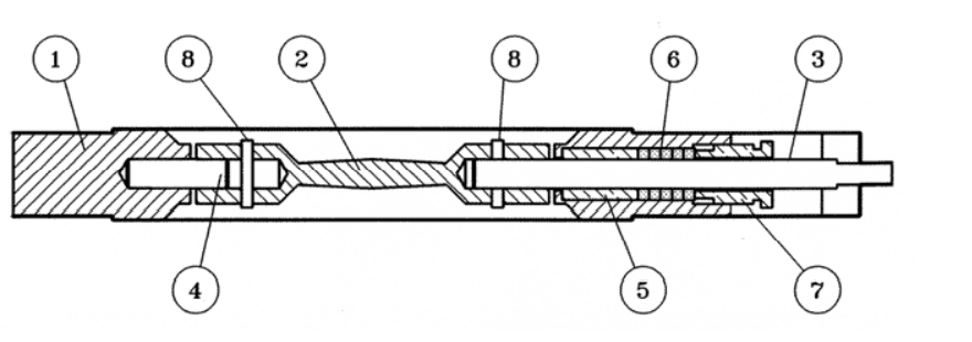
- Body
- Disc
- Power Shaft
- Idle Shaft
- Bushing
- Braided Packing
- Packing Nut
- Shaft Retaining Pin
16″ – 24″ Valve size

- Valve Body
- Valve Disc
- Power End Shaft
- Idle End Shaft
- Inboard Bushing
- Braided Packing (can be maintenanced in line)
- Packing Nut
- Shaft Retaining Pin
- Pipe Plug (sealed)
Chart or Graph
*Torque, Lb-In/PSI, Required for PDC swing thru valves with disc in closed position for temperatures up to 450 degrees F
*Below Torques only apply to normal clean service conditions
| VALVE SIZE | PRESSURE DROP ACROSS DISC IN CLOSED POSITION, PSI | ||||||||||||||||
|---|---|---|---|---|---|---|---|---|---|---|---|---|---|---|---|---|---|
| 0.5 | 1 | 5 | 10 | 15 | 20 | 25 | 30 | 40 | 50 | 60 | 70 | 80 | 90 | 100 | 125 | 150 | |
| 2 | 50 | 50 | 52 | 53 | 55 | 56 | 58 | 59 | 62 | 65 | 68 | 71 | 74 | 77 | 80 | 88 | 95 |
| 2.5 | 50 | 51 | 53 | 55 | 58 | 60 | 63 | 65 | 70 | 75 | 80 | 85 | 90 | 95 | 100 | 113 | 125 |
| 3 | 50 | 51 | 54 | 57 | 61 | 64 | 68 | 71 | 78 | 85 | 92 | 99 | 108 | 113 | 120 | 138 | 155 |
| 4 | 51 | 52 | 59 | 67 | 78 | 84 | 93 | 101 | 118 | 135 | 152 | 169 | 188 | 203 | 220 | 263 | – |
| 5 | 51 | 53 | 63 | 75 | 88 | 100 | 113 | 125 | 150 | 175 | 200 | 225 | 250 | 275 | 300 | – | – |
| 6 | 52 | 54 | 69 | 88 | 107 | 126 | 145 | 164 | 202 | 240 | 278 | 316 | 354 | – | – | – | – |
| 8 | 124 | 128 | 158 | 195 | 233 | 270 | 308 | 345 | 420 | 495 | 570 | 645 | 720 | 795 | – | – | – |
| VALVE SIZE | PRESSURE DROP ACROSS DISC IN CLOSED POSITION, PSI | ||||||||||||||||
|---|---|---|---|---|---|---|---|---|---|---|---|---|---|---|---|---|---|
| 0.5 | 1 | 3 | 5 | 8 | 10 | 13 | 15 | 20 | 25 | 30 | 35 | 40 | 45 | 50 | 60 | 70 | |
| 10 | 129 | 137 | 171 | 205 | 256 | 290 | 341 | 375 | 460 | 545 | 630 | 715 | 800 | 885 | 970 | 1140 | 1310 |
| 12 | 132 | 143 | 189 | 235 | 304 | 350 | 419 | 465 | 580 | 695 | 810 | 925 | 1040 | 1155 | 1270 | – | – |
| 14 | 139 | 157 | 231 | 305 | 416 | 490 | 601 | 675 | 860 | 1045 | 1230 | – | – | – | – | – | – |
| 16 | 223 | 245 | 335 | 425 | 560 | 650 | 785 | 875 | 1100 | 1325 | 1550 | 1775 | 2000 | – | – | – | – |
| 18 | 235 | 270 | 410 | 550 | 760 | 900 | 1100 | 1250 | 1600 | 1950 | 2300 | 2650 | – | – | – | – | – |
| VALVE SIZE | PRESSURE DROP ACROSS DISC IN CLOSED POSITION, PSI | ||||||||||||||||
|---|---|---|---|---|---|---|---|---|---|---|---|---|---|---|---|---|---|
| 0.5 | 1 | 2 | 4 | 5 | 7 | 9 | 10 | 12 | 14 | 15 | 17 | 19 | 20 | 22 | 24 | 25 | |
| 20 | 245 | 290 | 380 | 580 | 650 | 830 | 1010 | 1100 | 1280 | 1460 | 1550 | 1730 | 1910 | 2000 | 2180 | 2380 | 2450 |
| 22 | 261 | 322 | 444 | 688 | 810 | 1054 | 1298 | 1420 | 1664 | 1908 | 2030 | 2274 | 2518 | 2640 | – | – | – |
| 24 | 280 | 359 | 518 | 836 | 995 | 1313 | 1631 | 1790 | 2108 | 2426 | 2585 | 2903 | – | – | – | – | – |
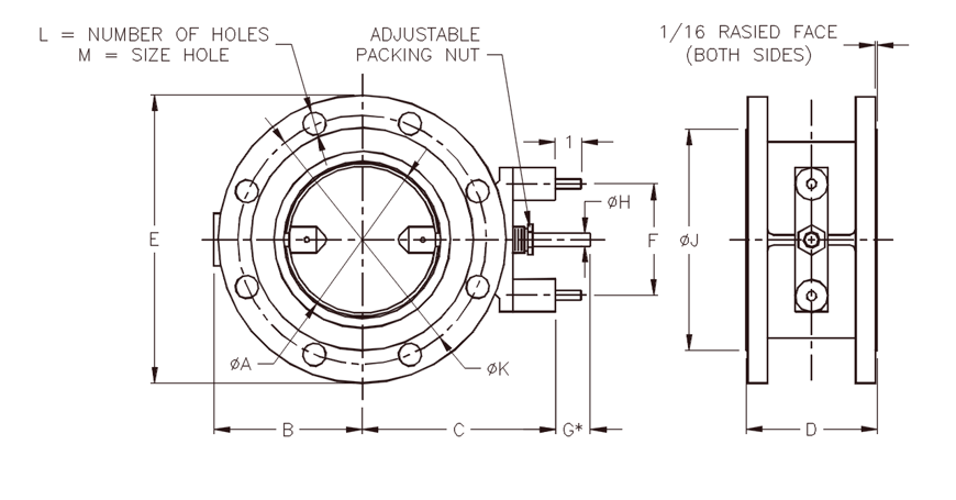
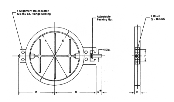
Typical Dimensions: 4″ thru 14″
| SIZE | A | B | C | D | E | F | H | Max ΔP | Approx wt (Lb.) |
|---|---|---|---|---|---|---|---|---|---|
| 2 | 2 | 3-7/8 | 5-3/8 | 1-1/2 | 3-7/8 | 4-1/4 | 1/2 | 150 | 9 |
| 2-1/2 | 2-1/2 | 4-1/8 | 5-5/8 | 1-1/2 | 4-5/8 | 4-1/4 | 1/2 | 150 | 10 |
| 3 | 3 | 4-3/8 | 5-7/8 | 1-1/2 | 5-1/8 | 4-1/4 | 1/2 | 150 | 11 |
| 4 | 4 | 4-7/8 | 6-3/8 | 1-1/2 | 6-3/8 | 4-1/4 | 1/2 | 125 | 12 |
| 5 | 5 | 5-3/8 | 6-7/8 | 1-1/2 | 7-1/2 | 4-1/4 | 1/2 | 100 | 15 |
| 6 | 6 | 5-7/8 | 7-3/8 | 1-1/2 | 8-1/2 | 4-1/4 | 1/2 | 80 | 17 |
| 8 | 8 | 7-3/4 | 9-5/8 | 1-7/8 | 10-3/4 | 5-1/8 | 3/4 | 90 | 32 |
| 10 | 10 | 8-3/4 | 10-5/8 | 1-7/8 | 13 | 5-1/8 | 3/4 | 70 | 40 |
| 12 | 12 | 9-3/4 | 11-5/8 | 1-7/8 | 15-1/4 | 5-1/8 | 3/4 | 50 | 50 |
| 14 | 13-1/8 | 10-1/2 | 12-1/8 | 1-7/8 | 16-3/8 | 5-1/8 | 3/4 | 30 | 70 |
Typical Dimensions: 16″ thru 24″
| Size (inch) | A | B | C | D | E | F | H | Max ΔP | Approx wt (Lb.) |
|---|---|---|---|---|---|---|---|---|---|
| 16 | 2 | 12-3/4 | 14-1/2 | 2-3/8 | 18-1/4 | 5-1/8 | 1 | 40 | 122 |
| 18 | 17-1/8 | 13-7/8 | 15-1/2 | 2-3/8 | 20-3/4 | 5-1/8 | 1 | 30 | 155 |
| 20 | 19-1/8 | 14-7/8 | 16-1/2 | 2-3/8 | 22-3/4 | 5-1/8 | 1 | 25 | 192 |
| 22 | 21-1/8 | 16-1/2 | 17-1/2 | 2-3/8 | 25 | 5-1/8 | 1 | 20 | 232 |
| 24 | 23-1/8 | 17-1/4 | 18-1/2 | 2-3/8 | 27 | 5-1/8 | 1 | 17 | 276 |
* “G” Length and configuration of the shaft end will vary to accommodate specific actuators. Refer to the accessory section for typical flatted, keywayed, and hexed end configurations available.
MAX. ∆P is based on 0° disc position, using standard materials of construction at a maximum temperature of 450° Fahrenheit.Consult factory for MAX. ∆P for elevated temperatures.
*Also Available in RPM Drilling in Most Sizes: Consult Factory
Cv Values for PDC Swing Thru Butterfly Valves
By definition, Cv is the flow coefficient of a control device or flow restriction. Cv is defined as the number of US gallons of 60°F water per minute which will flow through the given restriction with a one pound per square inch pressure drop.
Cv Values
(Flow in GPM of 60°F water at 1 psi pressure drop, specific gravity=1)
| VALVE SIZE | Disc Angle, Degress | ||||||||
|---|---|---|---|---|---|---|---|---|---|
| 10 | 20 | 30 | 40 | 50 | 60 | 70 | 80 | 90 | |
| 2 | 2 | 5 | 11 | 20 | 34 | 49 | 64 | 83 | 90 |
| 2.5 | 4 | 8 | 20 | 34 | 56 | 84 | 126 | 178 | 194 |
| 3 | 6 | 14 | 30 | 51 | 85 | 132 | 202 | 279 | 370 |
| 4 | 13 | 28 | 54 | 98 | 159 | 257 | 391 | 550 | 747 |
| 5 | 21 | 43 | 88 | 158 | 265 | 429 | 636 | 913 | 1272 |
| 6 | 30 | 63 | 126 | 228 | 382 | 632 | 955 | 1370 | 1999 |
| 8 | 53 | 111 | 225 | 406 | 680 | 1125 | 11698 | 2591 | 3853 |
| 10 | 83 | 174 | 351 | 635 | 1063 | 1759 | 2655 | 4052 | 6361 |
| 12 | 120 | 252 | 506 | 914 | 1531 | 2533 | 3826 | 5835 | 9164 |
| 14 | 143 | 302 | 606 | 1096 | 1835 | 3055 | 4584 | 6992 | 10981 |
| 16 | 191 | 400 | 805 | 1455 | 2436 | 4118 | 6388 | 9835 | 12266 |
| 18 | 244 | 513 | 1032 | 1865 | 3123 | 5279 | 8185 | 12608 | 15273 |
| 20 | 305 | 640 | 1287 | 2326 | 3896 | 6584 | 10209 | 15725 | 19612 |
| 22 | 372 | 781 | 1570 | 2838 | 4753 | 8033 | 12456 | 19186 | 23929 |
| 24 | 936 | 1882 | 3401 | 5696 | 9626 | 14926 | 22990 | 28674 | |

